HOWTO: Connecting a WaveShare ePaper display to a Raspberry Pi Pico W
In the realms of Helpful Information On The Internet, there are many sources that may or may not help you do fairly common interfacing tasks. However they’re not all superbly well written or appropriate for your specific use-case. In my case, I found the fact that various web-pages and documentation was either:
- Referring to older hardware (Raspberry Pi Pico not Pico W)
- Not at all clear whether pin numbers were physical or logical (GPIO)
…dangerously confusing. Here is my attempt to rectify that.
Disclaimer
I’ve only tested this on the following specific hardware:
..Although the wiring diagrams should be good for the earlier Pi Pico and any size of the WaveShare e-Paper module provided it’s one of the ones with the embedded controller and not the “raw” screens.
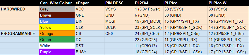
TL;DR how to map the pins
Discussion
Most of the online references, and indeed the sample code available for the ePaper devices, implicitly describe the logical pin numbers - the GPIO number - which actually is printed on the Pi Pico W underneath but does not directly correspond to the physical pin location.
The Pi Pico Pinout
diagram
is required to actually understand this, but even then it can get
confusing to work out what “mode” the pins are being used in. My
understanding is that the core SPI pins - DIN/MOSI and CLK/SCLK - are
using the SPI1 “mode” of physical pins 15 and 14 as SPI1_TX and
SPI1_SCK respectively. Whereas the CS, DC, RST and BUSY pins are
just being “mapped” onto available GPIO pins on the PiPico/W. This is
confusing since those pins are also used for SPI according to the
documentation. However, the fact that each of these pins is defined in the
sample ePaper code Python files with reference to the GPIO number and not
the physical pin or SPI value supports this belief.
It is also lucky for us (I think) that the sample code uses the SPI1 bus, since the Pi Pico W uses SPI0 for the onboard WiFi interface; I’m not sure this would be a deal breaker but it might be a complication worth avoiding.
But does it work?
Yes.
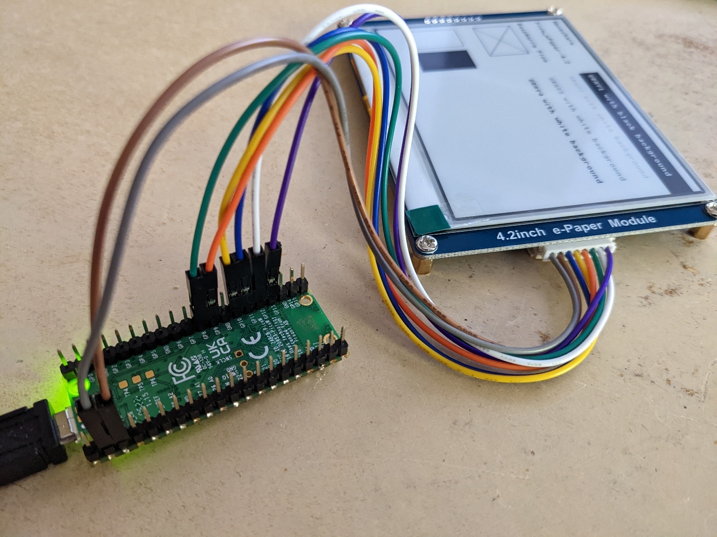
Although you can probably do a better job of the soldering of the header
pins than I did, it does in fact work and I got the demo file to run
(on the first attempt!) to display output. I should note that this did, in
fact, require patience because the REPL showed several iterations of
e-Paper busy / e-Paper busy release before any visible change was
made to the screen, and that was a black wipe/refresh before drawing
output. But, hey, if it’s millisecond refresh rate you wanted, then an
LCD/OLED display using HDMI should be your tool of choice not this
multi-second refreh ePaper stuff…